


 Direct purchase from the factory

![[US DIRECT] ATOMSTACK A5 M50 APP Control Dual-Laser Laser Engraving Cutting Machine Laser Engraver Cutter 5.5W Output Power Fixed-Focus 304 Mirror Stainless Steel Engraving DIY Laser Marking for Metal Wood Leather Vinyl](https://static.roymall.com/d/file/mall/titlepic/235/67803406-41f3-499a-afb7-154990584ff8.jpg?x-oss-process=image/resize,w_237/quality,Q_80/format,webp)


![[EU/US Direct]Raiser for LONGER RAY5 Engraver](https://static.roymall.com/d/file/mall/bigpic/235/65e9b76d-574a-4b4b-9c6c-02db18b89460.jpg?x-oss-process=image/resize,w_237/quality,Q_80/format,webp)
![[US/UK Direct] Refurbished ULTIMEA Nova S70 3.1.2 Soundbar 390W True Dolby Atmos Soundbar BassMax 4K Dolby Vision HDR Passthrough 3EQ Modes Wired Speaker Subwoofer](https://static.roymall.com/d/file/mall/titlepic/235/e1440062-c78c-4565-8aa7-f8857d749771.jpg?x-oss-process=image/resize,w_237/quality,Q_80/format,webp)


1.You can contact the customer service. for any question regarding the product.
2.Ask the question in English to get answer faster.
3.Keep your question short and to the point.
Questions:0/2000

 Multi Rotor PartsFPV SystemRadios & ReceiverBattery & ChargerTools & Bags & StorageConnector & Cable & WireRC ServosElectronic Learning ToysPlane & Parachute ToysSolar Powered ToysPottery Clay & ToolsPaper Art & DrawingBlocks & Track ToysModel BuildingDiecasts & Model ToysProtective GearsMotorcycle LightsCharger & Socket AdapterMotorcycle Engines & ComponentMotorcycle HelmetMotorcycle DIY KitsMotorcycle AccessoriesMotorcycle Alarm & SecurityCar Stickers & DecalsCar CoversWindow FoilsCar Protective FilmCar Protective Film Body ArmorLicense Plate AccessoriesDIY Electronic KitsElectronic Accessories & SuppliesModule ComponentsBoard & ShieldExpansion Board & ShieldSmart ModuleSensor & Detector ModulePower Supply ModuleRaspberry Pi & Orange PiSecurity Alarm SystemSmart Remote ControlWeather Station & ThermometerAccess Control & IntercomsHome Automatic KitsAutomation ModulesClocksHome Decor StickerDecorative PaintingDecorative CraftsStorage BagsStorage BoxesItems Storage & OrganizationSeedsWatering & IrrigationGarden LightsPest Control ProductsBathroom ApplianceShowerhead & AccessoriesBathroom Storage & OrganisationBathroom SafetyDoor Hardware & LocksIndustrial HardwareDecorative HardwarePackaging & ShippingStorage & OrganizationFurniture HardwareKitchen Tools & GadgetsDrinkware & Tea SetsBakeware & AccessoriesHome Brewing & Wine MakingKitchen Knife & CutleryBarbecue & Picnic SuppliesDinnerware & FlatwareXiaomi Kitchen Appliance
안전한 결제 보장

 무료 선물
무료 선물
 배송 정책
배송 정책 반품 정책
반품 정책
A part of the review has been auto-translated.

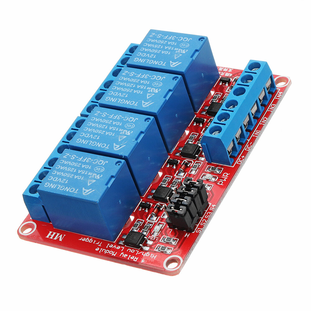
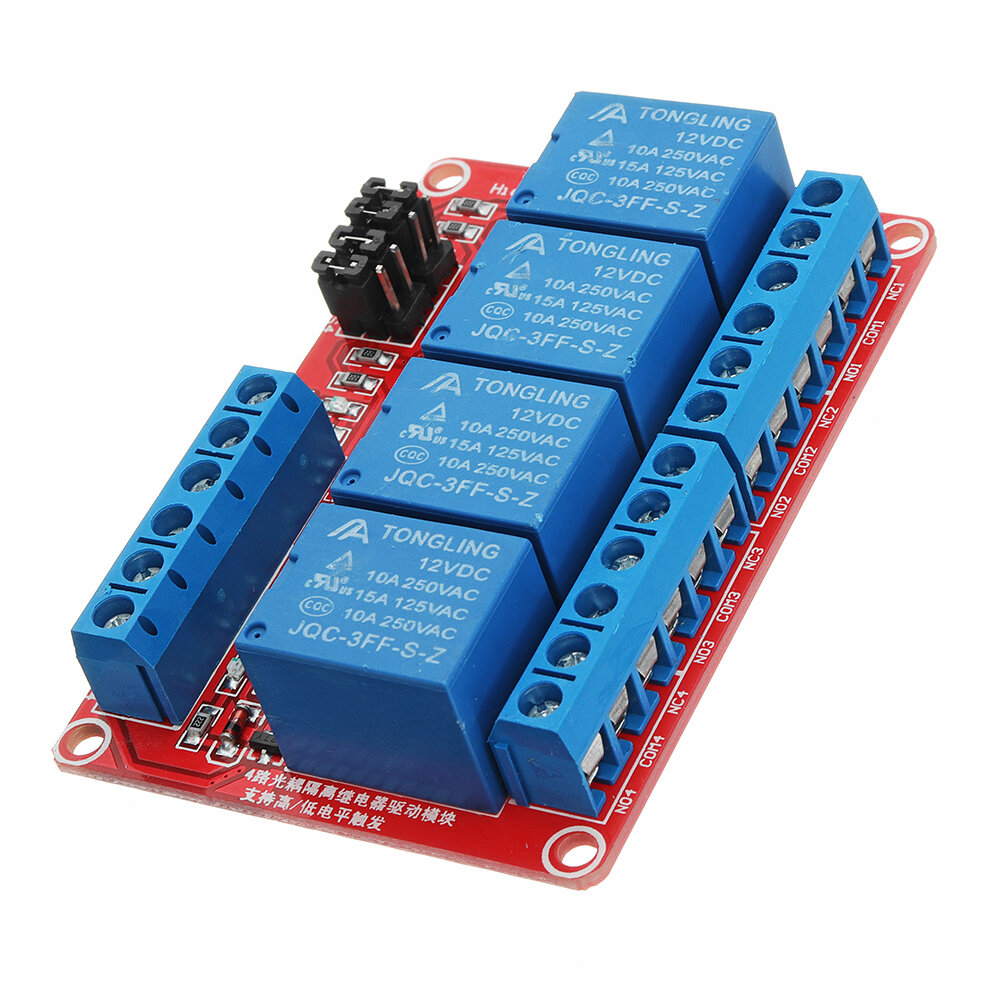
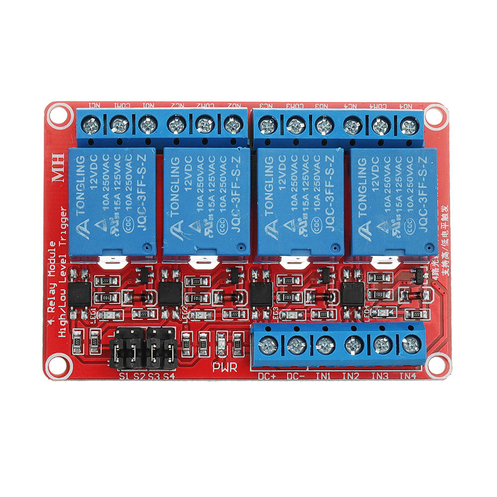
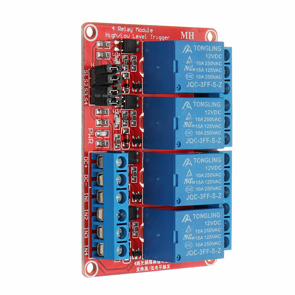
It's an "optocoupler" relay module operating at 12 Volt.
Does this mean that 12 V is galvanic isolated from the arduino, that should control the relays? My first impression was: I am missing a separate ground for the relay control and for the arduino!
However, after some study I discovered that you CAN operate the board with galvanic isolated 12 V and the arduino's 5 V.
How? Don't use the straps!!
So don't connect the 4 middle pins with straps to Ground or to VCC of the relay module, but connect these 4 pins to the arduino's ground!
Now the 12V and the arduino's 5V are galvanic isolated! See photo!

Item as described and expected. Fast delivery and service from Banggood :)
Tips:For questions about your order, place of delivery, product discount, taxation, delivery time, warranty, shipping, payment, exchange rate, and other questions unrelated to the product, please contact customer service.
A part of the QA has been auto-translated.
 0 Liked 장바구니에 추가됨
 0 Liked 장바구니에 추가됨
 0 Liked 장바구니에 추가됨
 0 Liked 장바구니에 추가됨
 0 Liked 장바구니에 추가됨
 0 Liked 장바구니에 추가됨
 0 Liked 장바구니에 추가됨
 0 Liked 장바구니에 추가됨
 0 Liked 장바구니에 추가됨
 0 Liked 장바구니에 추가됨
 0 Liked 장바구니에 추가됨
최신 브랜드 소식과 첫 주문 시 15% 할인을 받으세요.

Hi ?
How can we help?


